8 channel 16 bit ADC module
1. Module characteristics:
1. With industrial design, the design and material of the circuit are very particular. The connection of the input interface is convenient and reliable.
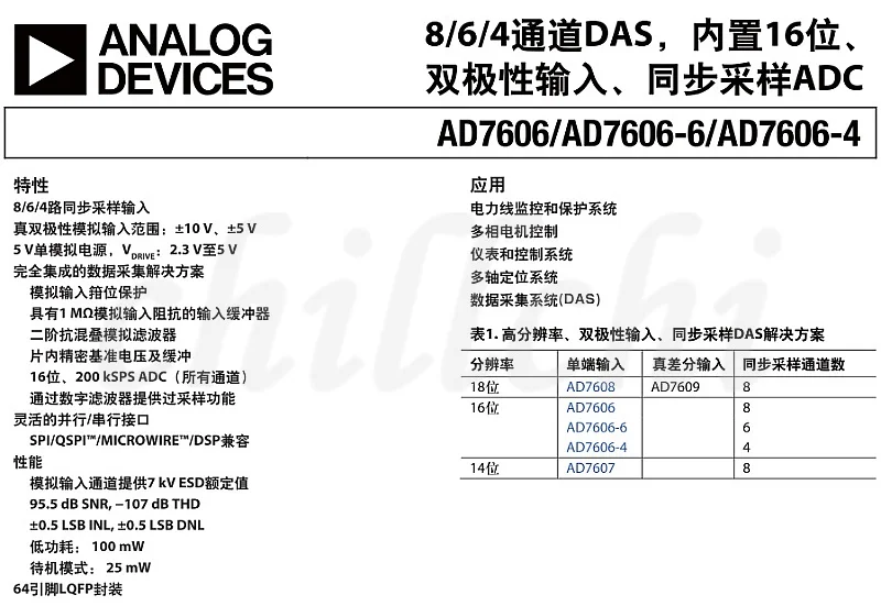
2, the AD7606 module is a 8 channel synchronous sampling and 16 bit high precision ADC module.
3, 8 analog input; the chip has a built-in preamplifier, which can be directly connected to the sensor output.
4, module input range: +-5V or +-10V can be set by changing the resistance on the board.
5, resolution 16;
6, the highest sampling frequency of AD7606 can reach 200KHz.
7, 16 bit bus interface. Interface IO level 3.3V, can be changed to 5V;
8, module single 5V power supply, chip built-in datum;
9, module size: 62mm*55mm;
Two.
1, module one;
2, FPGA and STM32 demonstration procedures;
Four. The chip Description:
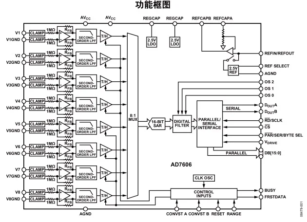
Chip control IO description
OS2 OS1 OS2: combinatorial state selection over sampling mode.
000 shows the maximum 200Ksps sampling rate without oversampling.
001 means 2 times over sampling, which means collecting 2 samples inside the hardware for average
010 means 4 times over sampling, which means collecting 4 samples inside the hardware for average
011 means 8 times over sampling, which means collecting 8 samples inside the hardware for average
100 means 16 times over sampling, which means collecting 16 samples inside the hardware for average
101 means 32 times over sampling, which means collecting 32 samples inside the hardware for average
110 means 64 times over sampling, which means collecting 64 samples inside the hardware for average
The higher the over sampling ratio is, the longer the ADC conversion time is, the lower the maximum sampling frequency can be obtained.
CVA, CVB: start the control signal of the AD conversion. CVA determines the 1-4 channel, and CVB determines the 5-8 channel.
2 signals can be staggered for a short time. In general, CVA and CVB can be paralleled in parallel.
RAGE: range range selection. 0 is positive and negative 5V, and 1 is positive and negative 10V.
RD: read the signal
RST: reset signal
BUSY: busy signal
CS: chip select signal
FRST: indicator signal for first channel samples
VIO: communication interface level
DB0-DB15: data bus


