+


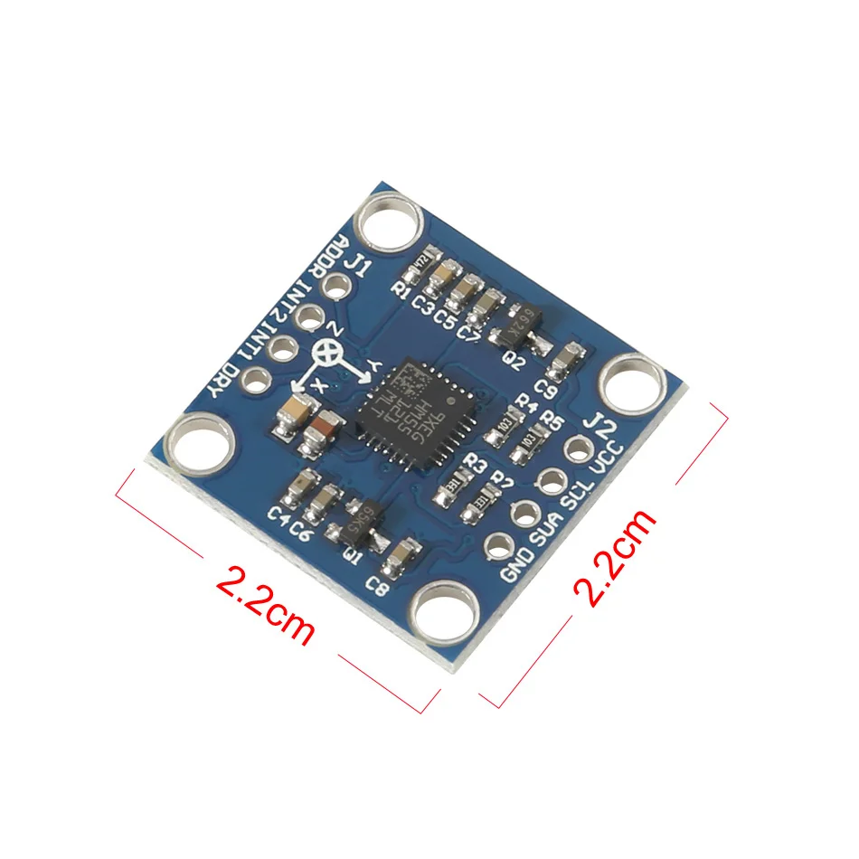
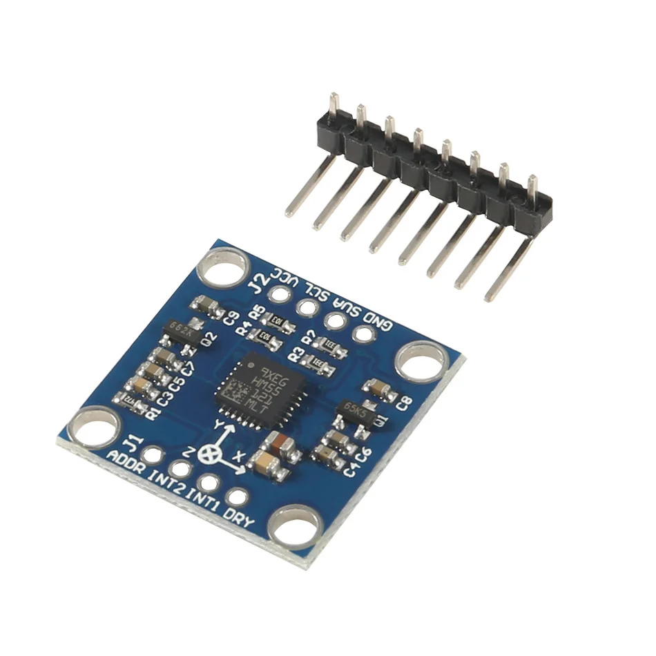
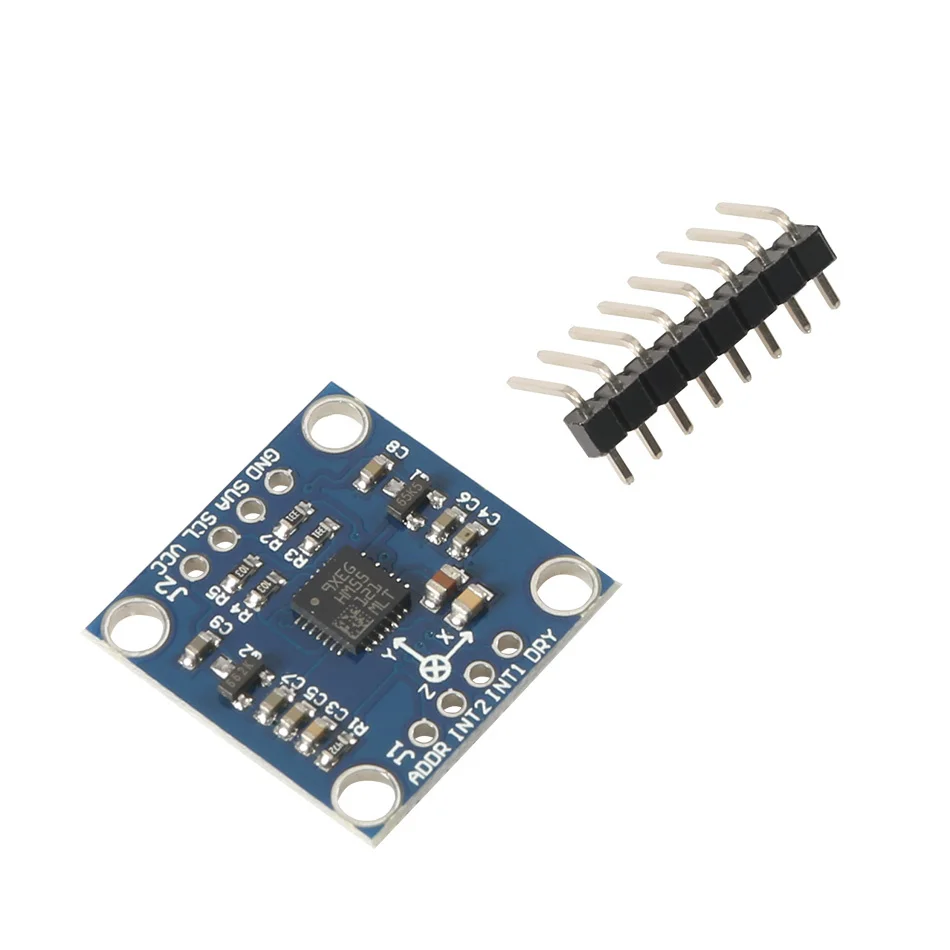
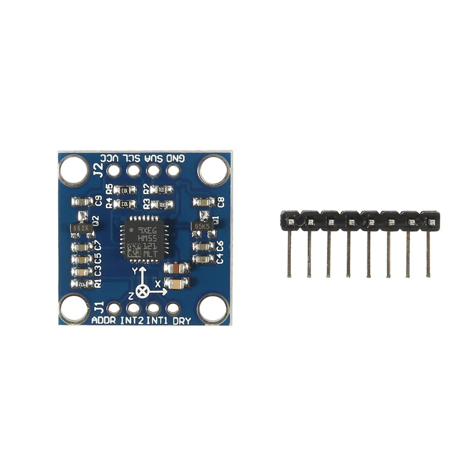
1 Buah GY-51 LSM303 LSM303D LSM303DLH HM55 Modul Akselerasi Kompas Elektronik Tiga Sumbu 3-5V
GY-51 LSM303 LSM303D LSM303DLH HM55 three axis electronic compass acceleration module 3-5V
Description:
Name: LSM303DLH module (three-axis magnetic field + triaxial acceleration)Chip built-in 12bit AD converter, 16-bit data outputHigh quality immersion gold PCB, machine welding process to ensure qualityUsing the chip: LSM303DLHPower supply: 3-5v (internal low dropout voltage regulation)Communication method: standard IIC communication protocolMagnetic field range:±1.3 / ±1.9 / ±2.5 /± 4.0 / ±4.7 / ±5.6 / ±8.1 gaussAcceleration range: ±2 g/±4 g/±8 gProvide 51 single chip test codeProvide STM32 test codeLSM303D related introduction:The LSM303DLH chip's accelerometer, magnetometer, A/D converter and signal processing circuit are integrated and still communicate with the processor via the I2C bus. In this way, 6-axis data detection and output is realized with only one chip, which reduces the design difficulty of the customer, reduces the occupied area of the PCB board, and reduces the device cost.The LSM303DLH requires few peripheral components and is easy to connect. The magnetometer and accelerometer each have an I2C bus and processor communication. If the customer's I/O interface level is 1.8V, Vdd_dig_M, Vdd_IO_A and Vdd_I2C_Bus can be connected to 1.8V, Vdd can be powered by 2.5V or more; if the customer interface level is 2.6V, except Vdd_dig_M requires 1.8V, Others can use 2.6V. As mentioned above, the LSM303DLH requires a set/reset circuit to maintain the main magnetic domain of the AMR. C1 and C2 are the external matching capacitors of the set/reset circuit. Since there are certain requirements for the set pulse and reset pulse, it is recommended that users do not arbitrarily modify the size of C1 and C2.To implement the electronic compass function, a three-axis magnetic sensor for detecting a magnetic field and a three-axis acceleration sensor are required. With the maturity of the micromechanical process, STMicroelectronics has introduced the LSM303DLH, a two-in-one sensor module that integrates a three-axis magnetometer and a three-axis accelerometer in one package, allowing users to design low-cost, high-performance electronics in a short period of time. compass. In this paper, LSM303DLH is taken as an example to discuss the working principle, technical parameters and implementation method of the electronic compass.1. ST integrated magnetometer and accelerometer sensor module LSM303DLH1.1 How the magnetometer worksIn the LSM303DLH, the magnetometer uses an anisotropic magneto-resistance material to detect the magnitude of magnetic induction in space. Such an alloy material having a crystal structure is sensitive to an external magnetic field, and a change in the strength of the magnetic field causes a change in the resistance value of the AMR itself.In the manufacturing process, a strong magnetic field is applied to the AMR to magnetize it in a certain direction to establish a main magnetic domain. The axis perpendicular to the main magnetic domain is called the sensitive axis of the AMR, as shown in FIG. In order to vary the measurement results in a linear manner, the metal wires on the AMR material are arranged at an angle of 45°, from which current flows. The direction of the main magnetic domain and current established by the initial strong magnetic field on the AMR material has an angle of 45 Å.When there is an external magnetic field Ha, the direction of the main magnetic domain on the AMR changes and is no longer the initial direction, then the angle θ between the direction of the magnetic field and the current also changes, as shown in Fig. 5. For AMR materials, the change in the angle θ causes a change in the AMR's own resistance and is linear.ST uses the Wheatstone bridge to detect changes in the AMR resistance. R1/R2/R3/R4 are AMR resistors of the same initial state, but R1/R2 and R3/R4 have opposite magnetization characteristics. When an external magnetic field is detected, the resistance of R1/R2 increases? R and R3/R4 decreases by R. Thus, in the absence of an external magnetic field, the output of the bridge is zero; and in the presence of an external magnetic field, the output of the bridge is a small voltage?V.1.2 Set/Reset CircuitDue to the influence of the external environment, the direction of the main magnetic domain on the AMR in the LSM303DLH will not remain permanently. The LSM303DLH has a built-in/reset circuit that periodically generates current pulses through the internal metal coil to restore the initial main magnetic domain, as shown in Figure 8. It should be noted that the set pulse and the reset pulse have the same effect, but the direction is different.The set/reset circuit brings many advantages to the LSM303DLH:1) Even if it encounters interference from strong external magnetic fields, the LSM303DLH can resume normal operation after the interference disappears without requiring the user to perform correction again.2) Accurate measurement can be achieved by maintaining the initial magnetization direction even if it is used for a long time, and it will not affect the measurement accuracy due to chip temperature variation or internal noise increase.3) Eliminate bridge deviation due to temperature drift.1.3 Performance parameters of LSM303DLHThe LSM303DLH integrates a three-axis magnetometer and a three-axis accelerometer with a digital interface. The magnetometer's measurement range is from 1.3 Gauss to 8.1 Gauss in 7 steps, which users can choose freely. And consistent measurement and the same sensitivity in a magnetic field environment up to 20 Gauss. It has a resolution of 8 mGauss and a 12-bit ADC internally to ensure accurate measurement of the magnetic field strength. Compared to magnetometers that use the Hall effect principle, the LSM303DLH has low power consumption, high accuracy, good linearity, and no temperature compensation.The LSM303DLH has an automatic detection function. When the control register A is set, the self-test circuit inside the chip generates an excitation signal of approximately the magnitude of the earth's magnetic field and outputs it. The user can judge whether the chip is working normally by outputting data.As a highly integrated sensor module, in addition to the magnetometer, the LSM303DLH also integrates a high-performance accelerometer. The accelerometer also uses a 12-bit ADC to achieve a measurement accuracy of 1 mg. The accelerometer operates in a low-power mode with sleep/wake-up capabilities to significantly reduce power consumption. At the same time, the accelerometer also integrates 6-axis direction detection and two programmable interrupt interfaces.For portable devices, the power consumption of the device is very important, directly affecting the standby time. The LSM303DLH can control the power mode of the magnetometer and accelerometer to put them into sleep or low power mode. And the user can adjust the data update frequency of the magnetometer and accelerometer to adjust the power consumption level. When the magnetometer data update frequency is 7.5 Hz and the accelerometer data update frequency is 50 Hz, the current consumption is typically 0.83 mA. In standby mode, the current consumption is less than 3uA.2. Ferromagnetic field interference and calibrationThe electronic compass mainly calculates the direction of the magnetic north pole by sensing the existence of the earth's magnetic field. However, since the earth's magnetic field is generally only a weak 0.5 Gauss, an ordinary mobile phone horn will still have a magnetic field of about 4 gauss when it is 2 cm apart. A mobile phone motor will have a magnetic field of about 6 gauss when it is 2 cm apart. This feature makes the measurement of the Earth's magnetic field on the surface of electronic equipment susceptible to interference from the electronic device itself.Magnetic field interference refers to the presence of a magnetic substance or a substance that can affect the strength of a local magnetic field, such that the earth's magnetic field at the position where the magnetic sensor is placed is deviated. As shown in Fig. 11, in the XYZ coordinate system of the magnetic sensor, the green circle represents the projection trajectory in the XY plane during the rotation of the earth's magnetic field vector around the z-axis, and without any external magnetic field interference, the trajectory will Will be a standard circle centered on O(0,0). When there is external magnetic field interference, the measured magnetic field strength vector α will be the vector sum of the earth magnetic field β and the interfering magnetic field γ at that point. Referred to as:It is generally believed that the disturbing magnetic field γ can be regarded as a constant vector at this point. There are many factors that can cause magnetic field interference, such as motors and horns placed on a circuit board, as well as materials containing metals such as iron-nickel-cobalt, such as shields, screws, resistors, LCD backplanes, and housings. A wire that also has a current through Ampere's law also produces a magnetic field, as shown in Figure 12.In order to calibrate these magnetic field disturbances from the board, the main job is to calculate γ by calculation.2.1 Plane calibration methodFor the calibration of the XY axis, the device equipped with the magnetic sensor rotates in the XY plane, equivalent to rotating the earth's magnetic field vector around the normal point O(γx, γy) perpendicular to the XY plane, and the red circle is The trajectory of the magnetic field vector projected in the XY plane during the rotation. This can find the position of the center of the circle ((Xmax + Xmin)/2, (Ymax + Ymin)/2). Similarly, the device can be rotated in the XZ plane to obtain the trajectory circle of the earth's magnetic field on the XZ plane. The magnetic field interference vector γ(γx, γy, γz) in space.2.2 Stereo 8-word calibration methodIn general, when the device with sensors rotates in all directions in the air, the spatial geometry of the measured values is actually a sphere, and all the sampling points fall on the surface of the ball, as shown in Figure 13. This is similar to a circle projected in a two-dimensional plane.In this case, the center O(γx, γy, γz), that is, the magnitude and direction of the fixed magnetic field interference vector, can be obtained from a sufficient number of sample points. The formula is as follows:The 8-word calibration method requires the user to perform 8-word sloshing in the air using the equipment to be calibrated. In principle, the normal direction of the device should be directed to all eight quadrants of the space.2.2 Ten-sided calibration methodSimilarly, the calibration can be achieved by the following 10-sided calibration method.3. Tilt compensation and navigation angle calculationAfter calibration, the electronic compass is ready for use on a horizontal surface. But more often the phone is not level, usually it has an angle with the water level. This angle affects the accuracy of the heading angle and requires tilt compensation by the acceleration sensor.For the attitude of an object in the air, the navigation system has already been defined, as shown in Figure 17, which is also used in Android. Pitch (Φ) is defined as the angle between the x-axis and the horizontal plane, and the illustrated direction is the positive direction; Roll (θ) is defined as the angle between the y-axis and the horizontal plane, and the direction shown is the positive direction. The error of the heading angle caused by the Pitch angle is shown in Fig. 18. It can be seen that an inclination angle of 10 degrees in the x-axis direction can cause an error of a maximum heading angle of 7-8 degrees.The tilting posture of the mobile phone in the air detects the components of the gravitational acceleration on the three axes through the 3-axis acceleration sensor, and then Pitch and Roll can be calculated by Equation 2.Many of the current popular android phones are equipped with a compass function. In order to achieve this function, only the 2-in-1 sensing module LSM303DLH provided by ST is required.
Brand Name : MKS GEN
Dissipation Power : /
Application : Computer
Package : SOP
Model Number : GY-51 LSM303 LSM303D LSM303DLH HM55 three axis
Supply Voltage : /
Origin : Mainland China
Type : Voltage Regulator
Condition : New
Operating Temperature : /
is_customized : Yes